Background
In VMware SD-WAN (Velocloud) version 4.0, both SD-WAN Edge and SD-WAN Gateway added the support of Bidirectional Forwarding Detection (BFD). The objective of this post is to document the configuration of enabling BFD for the BGP peering between the SD-WAN Gateway (working as Partner Gateway) and PE router. There will be ping test result to compare the Partner Gateway failover time when the BGP is with and without BFD enabled.
Test environment
Software Version:
SD-WAN Edge, also called Velocloud Edge (VCE): R400-20201002-GA-503bad0411
SD-WAN Gateway: R400-20201002-GA-503bad0411
Description of the test environment
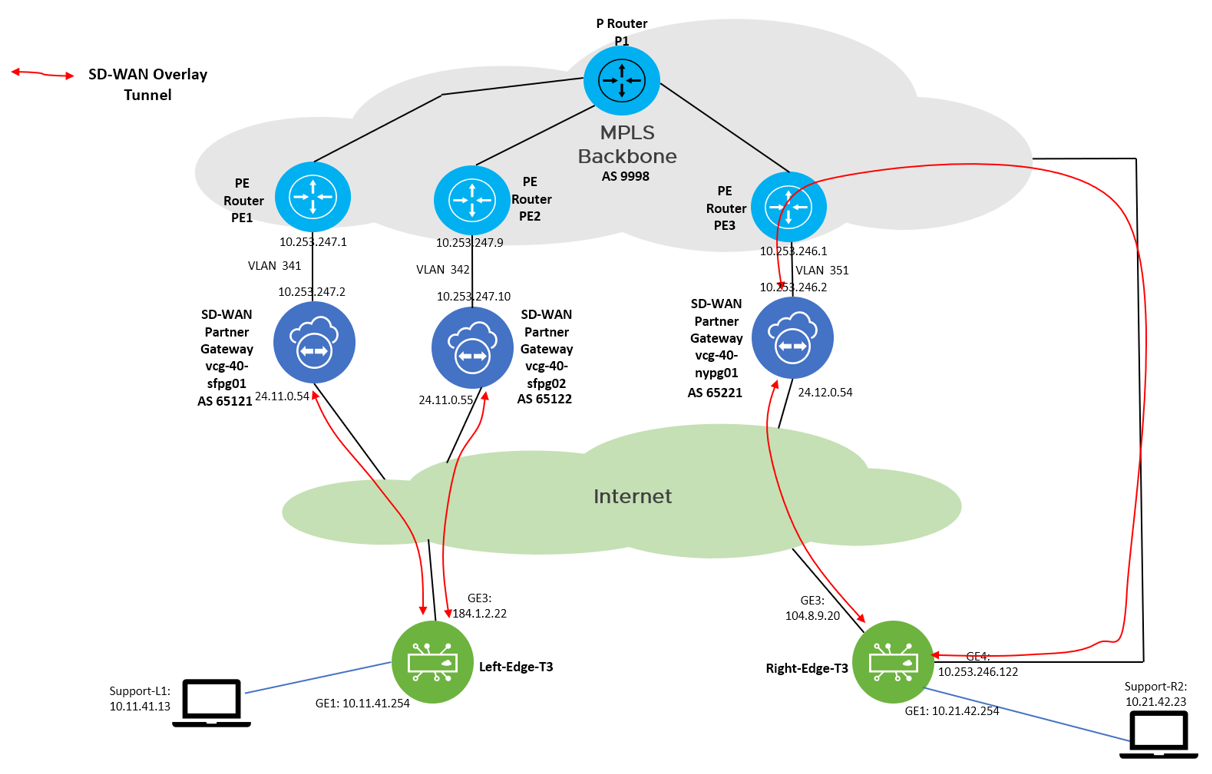
The test environment is a dark site (closed environment), let’s take a look on the test topology:

The environment can be considered as separate into two regions, where the “Left Region” consists of the SD-WAN Edge Left-Edge-T3, Partner Gateway (PGW) vcg-40-sfpg01 and vcg-40-sfpg02, and PE routers PE1 and PE2. The “Right Region” consists of the SD-WAN Edge Right-Edge-T3, Partner Gateway vcg-40-nypg01 and PE3.
The focus of the test is on the Left-Edge-T3 which assigned two partner gateways, with primary PGW vcg-40-sfpg01 and secondary PGW vcg-40-sfpg02. Under normal situation, the traffic path (normal path) from Support-L1 (10.11.41.13) to Support-R2 (10.21.42.23) is: Left-Edge-T3 –> vcg-40-sfpg01 –> PE1 –> PE3 –> vcg-40-nypg01 –> Right-Edge-T3. In case vcg-40-sfpg01 failed, the secondary PGW vcg-40-sfpg02 will pick up the traffic, then the traffic path (backup path) from Support-L1 (10.11.41.13) to Support-R2 (10.21.42.23) will become: Left-Edge-T3 –> vcg-40-sfpg02 –> PE2 -> PE3 –> vcg-40-nypg01 –> Right-Edge-T3. The return path will be ensured to be symmetric, the related configuration will be documented in the configuration section.
In this post, we will compare the failover time from the normal path to the backup path for with and without BFD between the PGW and PE router.
Note: The PE router is Cisco IOL in this test environment.
SD-WAN Edge, PGW and PE router configurations – without BFD
In this section, the configuration of the SD-WAN Edge, SD-WAN Gateway and PE router will be documented for the scenario without BFD.
Configuration of SD-WAN Edge
Left-Edge-T3
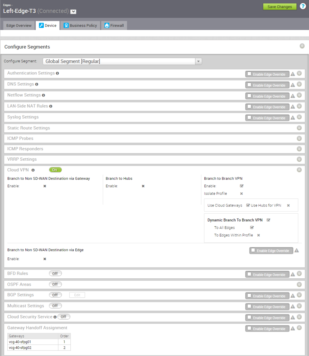
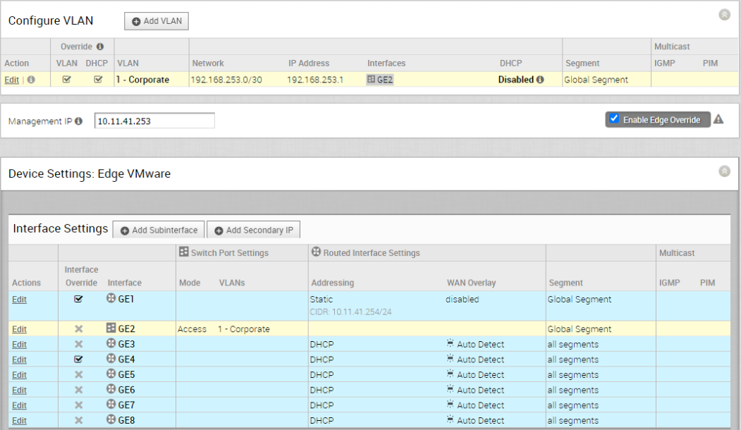
From the above screen capture (Figure 2 and 3), Left-Edge-T3 gets assigned with two PGW with primary PGW vcg-40-sfpg01 and secondary PGW vcg-40-sfpg02. The LAN facing interface is GE1 with IP address 10.11.41.254
Right-Edge-T3
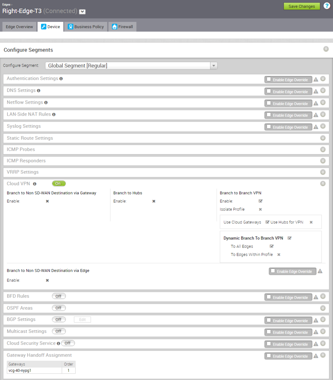
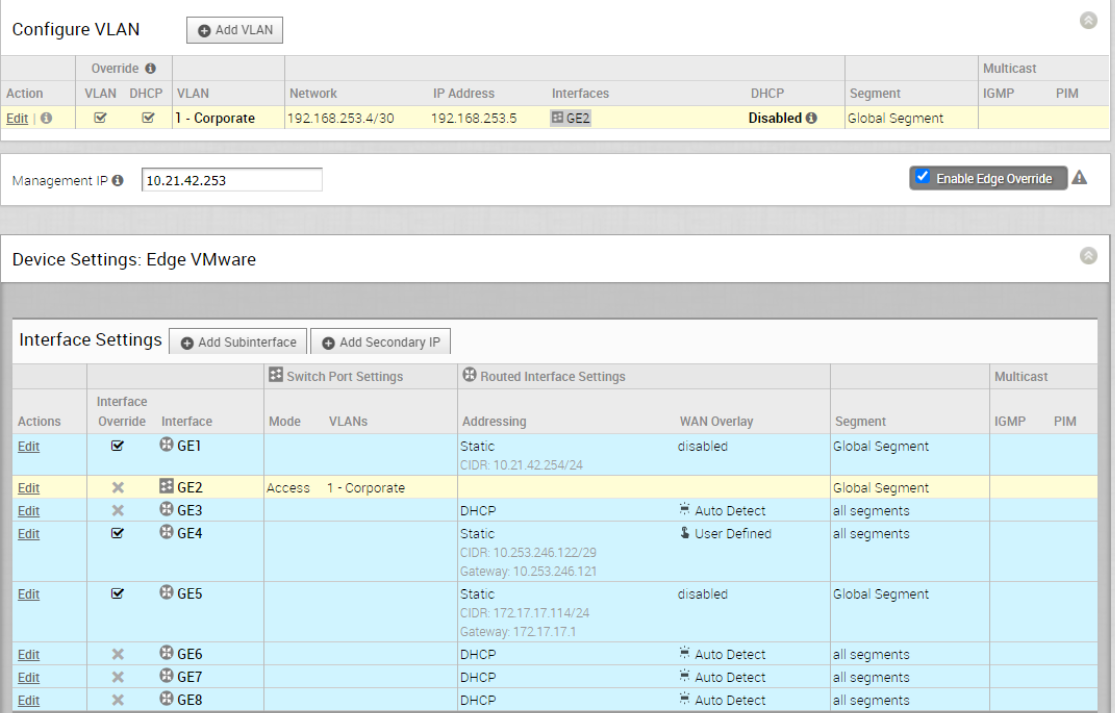
From the above screen capture, Right-Edge-T3 gets assigned with one PGW vcg-40-nypg01. The LAN facing interface is GE1 with IP address 10.21.42.254. Since there is no PGW failover test will be performed on Right-Edge-T3, so no redundant PGW is assigned.
Configuration of SD-WAN Gateway, Partner Gateway
vcg-40-sfpg01
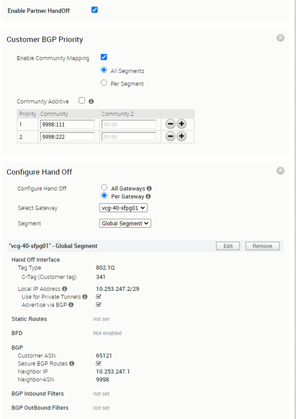
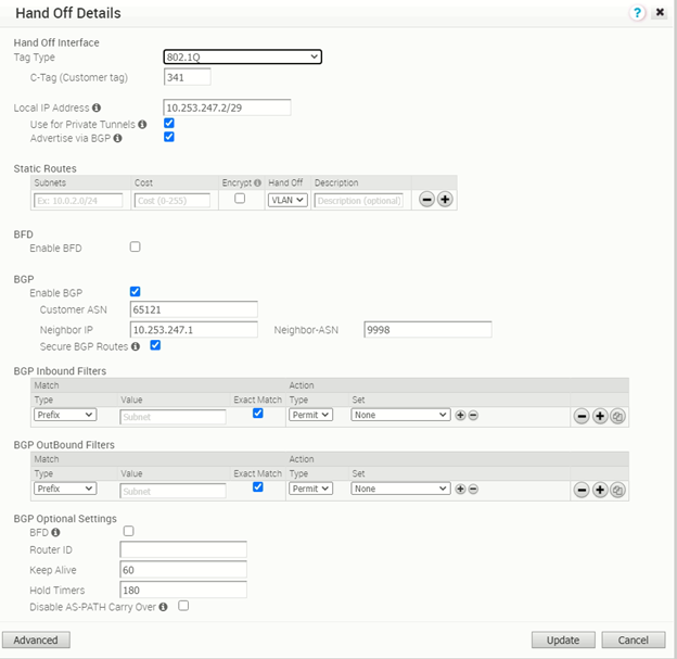
The PGW vcg-40-sfpg01 is configured with IP address 10.253.247.2/29, with AS number 65121. It is peering with PE router PE1 with AS number 9998 and IP address 10.253.247.1. The BGP timer is with default value where keep alive is 60s and hold timers is 180s. The BFD is disabled.
vcg-40-sfpg02
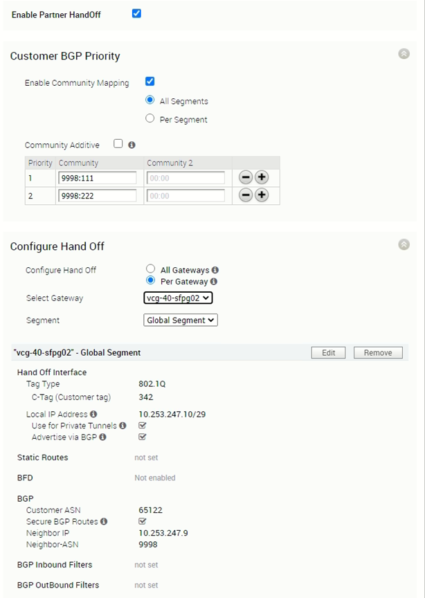
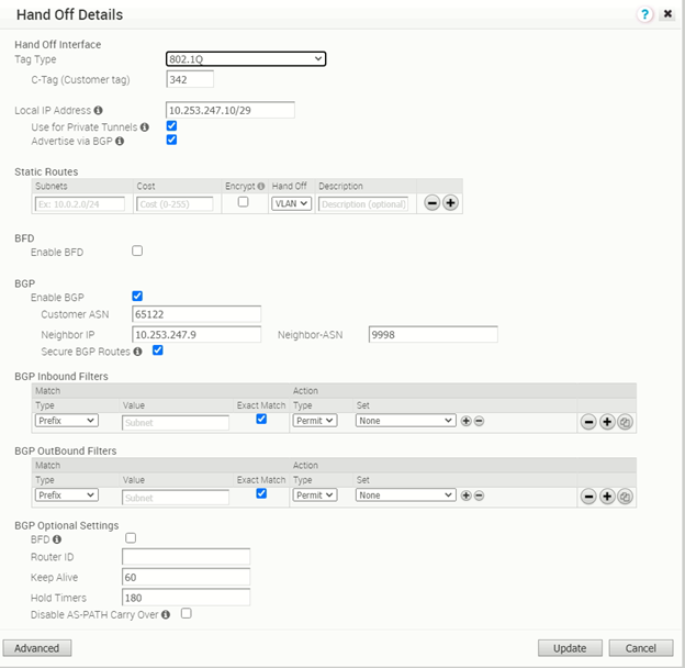
The PGW vcg-40-sfpg02 is configured with IP address 10.253.247.10/29, with AS number 65122. It is peering with PE router PE2 with AS number 9998 and IP address 10.253.247.9. The BGP timer is with default value where keep alive is 60s and hold timers is 180s. The BFD is disabled.
vcg-40-nypg01
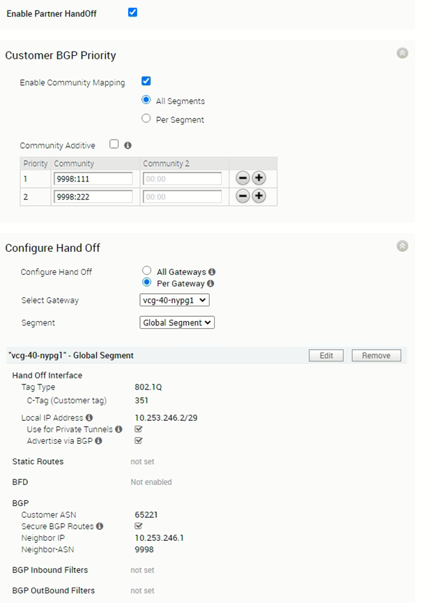
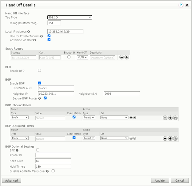
Including the configuration of the vcg-40-nypg02 for completeness.
Configuration of PE router
Since the focus of this post is the SD-WAN components, not the PE router, only related configuration of the PE router will be show. The VRF being used in the test is called Customer40b.
PE1
!
! sub-interface for this SD-WAN Customer
!
interface Ethernet0/2.341
 encapsulation dot1Q 341
 ip vrf forwarding Customer40b
 ip address 10.253.247.1 255.255.255.248
!
! BGP configuration to peer with PGW vcg-40-sfpg01
!
router bgp 9998
 address-family ipv4 vrf Customer40b
  network 10.253.247.0 mask 255.255.255.248
  network 10.253.247.120 mask 255.255.255.248
  neighbor 10.253.247.2 remote-as 65121
  neighbor 10.253.247.2 activate
  neighbor 10.253.247.2 send-community both
  neighbor 10.253.247.2 soft-reconfiguration inbound
  neighbor 10.253.247.2 route-map comm-set-localpref in
 exit-address-family
PE2
!
! sub-interface for this SD-WAN Customer
!
interface Ethernet0/2.342
 encapsulation dot1Q 342
 ip vrf forwarding Customer40b
 ip address 10.253.247.9 255.255.255.248
!
! BGP configuration to peer with PGW vcg-40-sfpg02
!
router bgp 9998
 address-family ipv4 vrf Customer40b
  network 10.253.247.8 mask 255.255.255.248
  network 10.253.247.128 mask 255.255.255.248
  neighbor 10.253.247.10 remote-as 65122
  neighbor 10.253.247.10 activate
  neighbor 10.253.247.10 send-community both
  neighbor 10.253.247.10 soft-reconfiguration inbound
  neighbor 10.253.247.10 route-map comm-set-localpref in
 exit-address-family
Configuration to ensure the traffic path is symmetric
Although the Left-Edge-T3 is aware the vcg-40-sfpg01 is the primary PGW as it is at order position #1, the MPLS backbone also need to ensure the return traffic prefer landing on PE1 instead of landing on PE2. This is done by auto community mapping at the PGW and route-map to adjust local preference at the PE router.
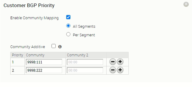
PGW is configured with community mapping with priority #1 PGW routes come with community 9998:111 (655229039) and priority #2 PGW routes come with community 9998:222 (655229150). That means, for the routes advertised by vcg-40-sfpg01 to the PE1, those routes will be having community 9998:111. For the routes advertised by vcg-40-sfpg02 to the PE2, those routes will be having community 9998:222.
The following configurations are the route-map comm-set-localpref to make PE1 is the preferred return path as route from vcg-40-sfpg01 is set with local preference of 200 while route from vcg-40-sfpg02 is set with local preference of 101.
PE1 route-map configuration:
!
ip community-list standard comm-priority1 permit 655229039
ip community-list standard comm-priority2 permit 655229150
!
! Set local preference to 200 when route comes with community 9998:111, set local preference to 101 when route comes with community 9998:222
!
route-map comm-set-localpref permit 10
 match community comm-priority1
 set local-preference 200
!
route-map comm-set-localpref permit 20
 match community comm-priority2
 set local-preference 101
!
! BGP configuration to peer with PGW vcg-40-sfpg01
!
router bgp 9998
 address-family ipv4 vrf Customer40b
  network 10.253.247.0 mask 255.255.255.248
  network 10.253.247.120 mask 255.255.255.248
  neighbor 10.253.247.2 remote-as 65121
  neighbor 10.253.247.2 activate
  neighbor 10.253.247.2 send-community both
  neighbor 10.253.247.2 soft-reconfiguration inbound
  neighbor 10.253.247.2 route-map comm-set-localpref in
 exit-address-family
The same route-map, hence same mechanism is applied to PE2 as well, the configuration of the PE2 route-map is like a mirror copy of PE1, so it is not repeated here.
Verification on SD-WAN Edge, PGW and PE router
The section will perform some verification to ensure the SD-WAN Edge, PGW, PE router has learnt the route properly.
Verification on SD-WAN Edge
Left-Edge-T3:
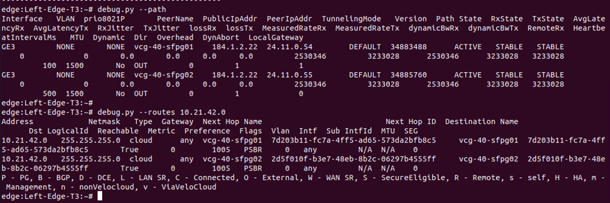
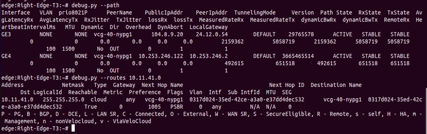
The above figure is the screen capture of output of “debug.py –path” and “debug.py –routes 10.21.42.0”. The output confirmed:
- Left-Edge-T3 is able to form overlay tunnel to vcg-40-sfpg01 and vcg-40-sfpg02
- Left-Edge-T3 learnt the route 10.21.42.0/24 from both vcg-40-sfpg01 and vcg-40-sfpg02 where vcg-40-sfpg01 is the preferred Next Hop.
Right-Edge-T3:
The above figure is the screen capture of output of “debug.py –path” and “debug.py –routes 10.11.41.0”. The output confirmed:
- Right-Edge-T3 is able to form overlay tunnels to vcg-40-nypg01.
- Right-Edge-T3 learnt the route 10.11.41.0/24 from vcg-40-nypg01.
Verification on PGW
vcg-40-sfpg01:
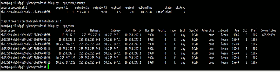
The above figure (Figure 15) is the screen capture of output of “debug.py –bgp_view_summary” and “debug.py –bgp_view” of PGW vcg-40-sfpg01. The output confirmed:
- PGW vcg-40-sfpg01 has successfully established BGP peer with PE1 (10.253.247.1)
- PGW vcg-40-sfpg01 learnt some routes from PE1, including the route 10.21.42.0/24
vcg-40-sfpg02:
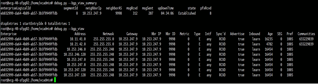
The above figure (Figure 16) is the screen capture of output of “debug.py –bgp_view_summary” and “debug.py –bgp_view” of PGW vcg-40-sfpg02. The output confirmed:
- PGW vcg-40-sfpg02 has successfully established BGP peer with PE2 (10.253.247.9).
- PGW vcg-40-sfpg02 learnt some routes from PE2, including the route 10.21.42.0/24.
vcg-40-nypg01
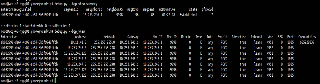
The above figure is the screen capture of output of “debug.py –bgp_view_summary” and “debug.py –bgp_view” of PGW vcg-40-nypg01. The output confirmed:
- PGW vcg-40-nypg01 has successfully established BGP peer with PE3 (10.253.246.1).
- PGW vcg-40-nypg01 learnt some routes from PE3, including the route 10.11.41.0/24.
Verification on PE router
PE1
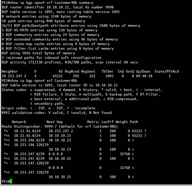
The above figure (Figure 18) is the screen capture of output of “show ip bgp vpnv4 vrf <VRF name> summary” and “show ip bgp vpnv4 vrf <VRF name>” of PE1. The output confirmed:
- PE1 successfully having BGP peer with vcg-40-sfpg01 (10.253.247.2).
- PE1 successfully learnt the route 10.11.41.0/24 from PGW vcg-40-sfpg01.
- PE1 successfully learnt the route 10.11.42.0/24 from MPLS backbone.
PE2
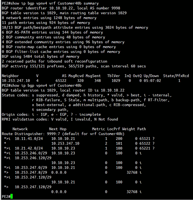
The above figure is the screen capture of output of “show ip bgp vpnv4 vrf <VRF name> summary” and “show ip bgp vpnv4 vrf <VRF name>” of PE2. The output confirmed:
- PE2 successfully having BGP peer with vcg-40-sfpg02 (10.253.247.10).
- PE2 successfully learnt the route 10.11.41.0/24 from PGW vcg-40-sfpg02 (and also from PE1 as PE1 learnt this route from vcg-40-sfpg01).
- PE2 successfully learnt the route 10.21.42.0/24 from MPLS backbone.
PE3
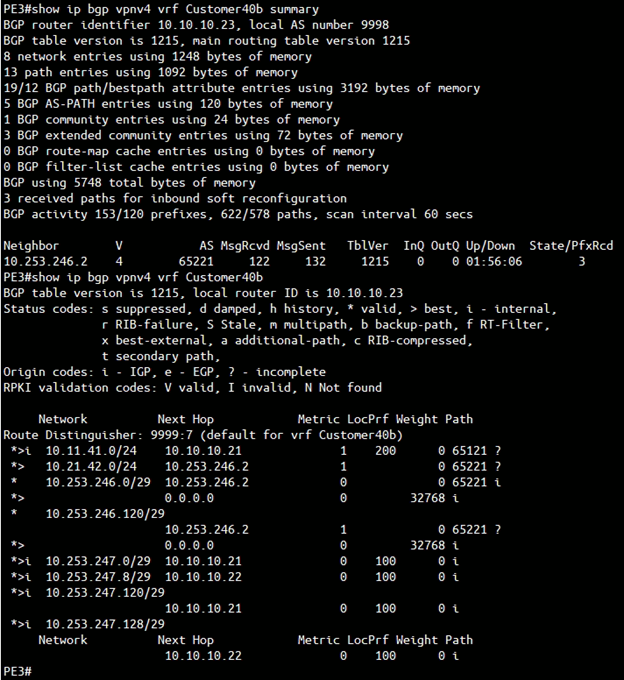
The above figure is the screen capture of output of “show ip bgp vpnv4 vrf <VRF name> summary” and “show ip bgp vpnv4 vrf <VRF name>” of PE3. The output confirmed:
- PE3 successfully having BGP peer with vcg-40-nypg01 (10.253.246.2).
- PE3 successfully learnt the route 10.21.42.0/24 from PGW vcg-40-nypg01.
- PE3 successfully learnt the route 10.11.41.0/24 from MPLS backbone. Note that the Next Hop is 10.10.10.21 which is the PE1 loopback IP address, the local preference is 200. This means the route-map on PE1 and PE2 is working, such that packets prefer going to PE1 for destination 10.11.41.0/24.
PGW Failover Test – without BFD
The test is to test how long does it take for the traffic to switch from vcg-40-sfpg01 to vcg-40-sfpg02. In order to perform this test, the Linux machine support-L1 (10.11.41.13) issue a continuous ping to support-R2 (10.21.42.23). In the middle of the ping, the vcg-40-sfpg01 will get power off, and the time required to fail over will get recorded.
Before the ping failover test, a traceroute from support-L1 (10.11.41.13) to support-R2 (10.21.42.23) is capture as follow:
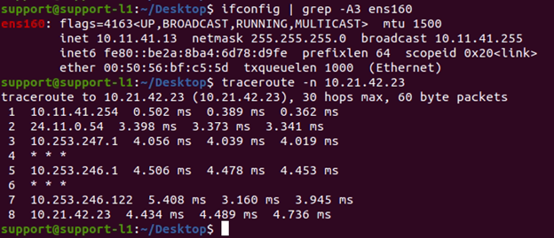
This traceroute confirmed the traffic path is “Left-Edge-T3 –> vcg-40-sfpg01 –> PE1 –> PE3 –>vcg-40-nypg01 –> Right-Edge-T3”
The test method is having Support-L1 (10.11.41.13) issue a continuous ping to Support-R2 (10.21.42.23), in the middle of the ping, PGW vcg-40-sfpg01 gets powered off. The following show the test result:
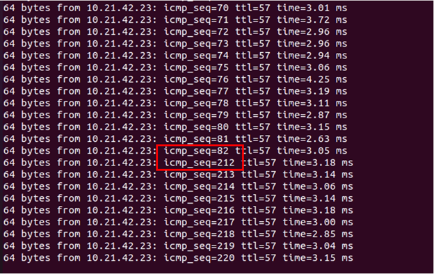
From the ping screen capture, the PGW vcg-40-pg01 get powered off right after the icmp sequence number 82. There are 129 ping missed during the failover, which is roughly around 130 seconds.
The reader might wonder why the failover takes so long, since the SD-WAN Edge Left-Edge-T3 is having Overlay Tunnel to both vcg-40-sfpg01 and vcg-40-sfpg02, when vcg-40-sfpg01 gets powered off, the corresponding Overlay Tunnel gets terminated. As a result, Left-Edge-T3 should be able to switch to vcg-40-sfpg02 in sub-second. This understanding is correct. But let’s look at the diagram again to refresh the memory:
The failover takes long time because of the return traffic. The PE1 is configured to have route map to attract the return traffic. In order for the return traffic to be able to switch from PE1 to PE2, PE1 must stop advertising the 10.11.41.0/24 route. PE1 will stop advertising when the BGP peer between PE1 and vcg-40-sfpg01 is down, with the default timer (60s keepalive and 180s hold timer), it can take a maximum of 180 seconds for the BGP peer to go down.
One of the options to speed up the failover is having a smaller value of keepalive and hold timer. The following is the screen capture of repeating the same ping test with 3s keepalive and 9s hold timer:
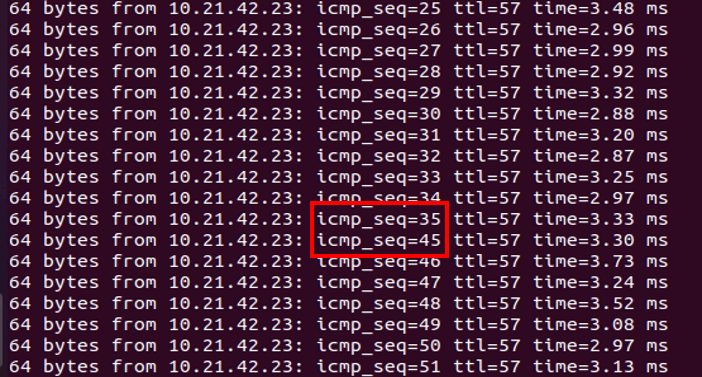
From the ping screen capture, the PGW vcg-40-pg01 get powered off right after the icmp sequence number 35. There are 9 ping missed during the failover, which the failover is roughly around 9-10 seconds.
PGW and PE Router Configurations – with BFD
In this section, BFD will be enabled in the SD-WAN Gateways and PE routers. Other devices like the SD-WAN Edge will maintain the existing configuration.
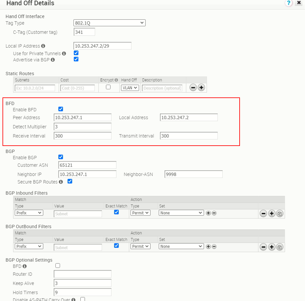
SD-WAN Gateway (Partner Gateway) – with BFD
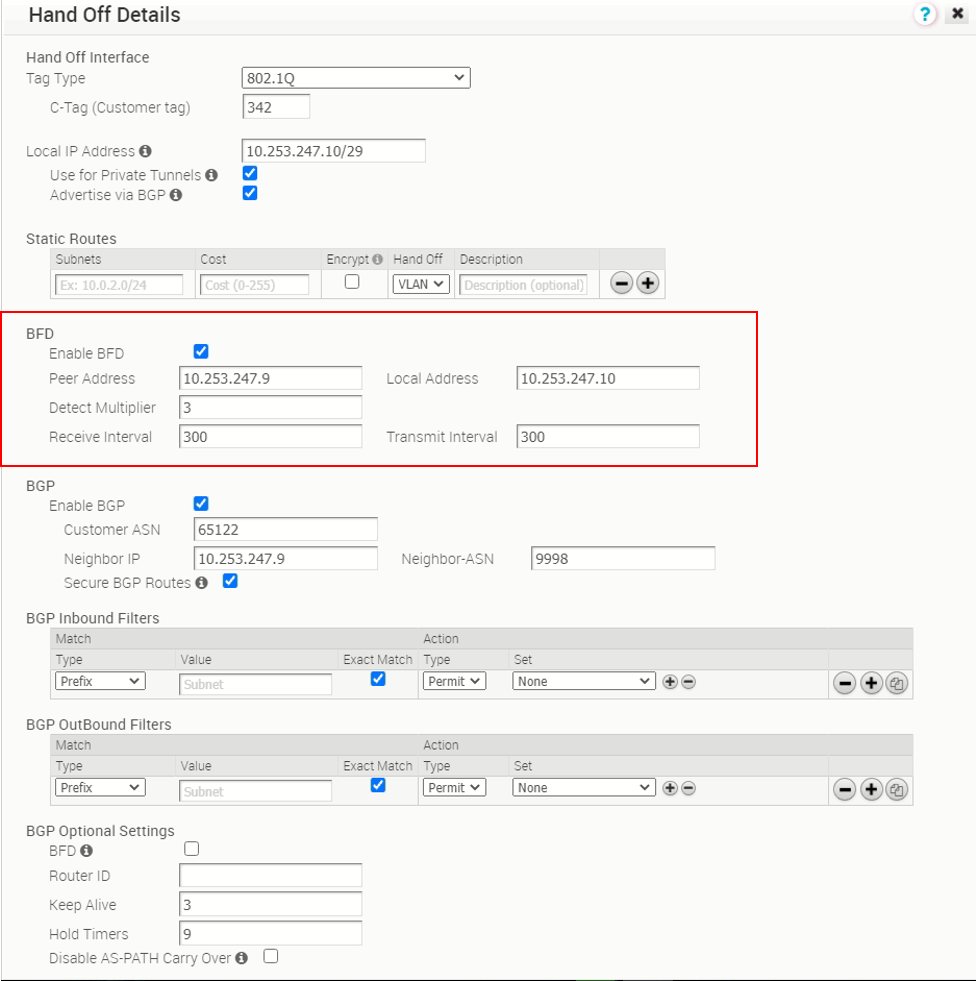
The follow two screen captures show the PGW (vcg-40-sfpg01 and vcg-40-sfpg02) BGP peer with BFD enabled. In this test, the receive interval and transmit interval are both 300ms, the multiplier is 3.
PE router – with BFD
PE1 configuration by enabling BFD for BGP peer 10.253.247.2
!
interface Ethernet0/2.341
 encapsulation dot1Q 341
 ip vrf forwarding Customer40b
 ip address 10.253.247.1 255.255.255.248
 bfd interval 300 min_rx 300 multiplier 3
 no bfd echo
!

router bgp 9998
 address-family ipv4 vrf Customer40b
  network 10.253.247.0 mask 255.255.255.248
  network 10.253.247.120 mask 255.255.255.248
  neighbor 10.253.247.2 remote-as 65121
  neighbor 10.253.247.2 fall-over bfd
  neighbor 10.253.247.2 activate
  neighbor 10.253.247.2 send-community both
  neighbor 10.253.247.2 soft-reconfiguration inbound
  neighbor 10.253.247.2 route-map comm-set-localpref in
 exit-address-family
PE2 configuration by enabling BFD for BGP peer 10.253.247.10
!
interface Ethernet0/2.342
 encapsulation dot1Q 342
 ip vrf forwarding Customer40b
 ip address 10.253.247.9 255.255.255.248
 bfd interval 300 min_rx 300 multiplier 3
 no bfd echo
!

router bgp 9998
 address-family ipv4 vrf Customer40b
  network 10.253.247.8 mask 255.255.255.248
  network 10.253.247.128 mask 255.255.255.248
  neighbor 10.253.247.10 remote-as 65122
  neighbor 10.253.247.10 fall-over bfd
  neighbor 10.253.247.10 activate
  neighbor 10.253.247.10 send-community both
  neighbor 10.253.247.10 soft-reconfiguration inbound
  neighbor 10.253.247.10 route-map comm-set-localpref in
 exit-address-family
The newly added configuration to enable BFD in the PE router is marked with italic in the above configuration snippets.
NOTE: In the PE router sub-interface using for the test vrf, that is vrf Customer40b, the “no bfd echo” command is entered to disable the BFD echo mode. As of the VMware SD-WAN version 4.0, BFD echo mode is not supported, only BFD asynchronous mode is supported.
Verification of the BFD status
Verification of BFD status at the PGW
There is now a “Gateway BFD Sessions” tab under “Monitor –> Routing –> BFD”
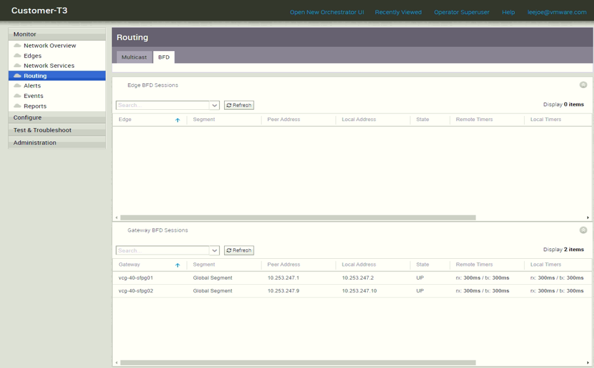
From the “Gateway BFD Sessions” GUI, we can see both vcg-40-sfpg01 and vcg-40-sfpg02 are having “UP” state of the BFD with the corresponding BGP peer, which means the BFD is working. In case more detail information is needed, in the PGW shell, there are two commands can check the BFD status, they are “debug.py –bfd_info” and “debug.py –bfdd_dump”. The output below is from PGW vcg-40-sfpg01 which shows the BFD peer is with “up” status. The following snippet shows the BFD debug.py output of vcg-40-sfpg01:
vcadmin@vcg-40-sfpg01:~$ sudo /opt/vc/bin/debug.py --bfd_info
EnterpriseId SEG Peer Address Local Address Detect Multiplier Transmit Interval Receive Interval Status
eb032999-da64-4b09-ab57-3b5f9949ffdb 0 10.253.247.1 10.253.247.2 3 300 300 UP
vcadmin@vcg-40-sfpg01:~$ sudo /opt/vc/bin/debug.py --bfdd_dump
show running-config
Building configuration…
Current configuration:
!
frr version 7.0
frr defaults traditional
hostname vcg-40-sfpg01
log file /var/log/bfdd.log
!
password zebra
!
line vty
access-class vty
!
bfd
peer 10.253.247.1 local-address 10.253.247.2 vrf [eb032999-da64-4b09-ab57-3b5f9949ffdb:0:1]
no shutdown
!
!
end
show bfd peers
BFD Peers:
peer 10.253.247.1 local-address 10.253.247.2 vrf [eb032999-da64-4b09-ab57-3b5f9949ffdb:0:1]
ID: 3238898200
Remote ID: 1
Status: up
Uptime: 34 minute(s), 48 second(s)
Diagnostics: ok
Remote diagnostics: ok
Local timers:
Receive interval: 300ms
Transmission interval: 300ms
Echo transmission interval: 50ms
Remote timers:
Receive interval: 300ms
Transmission interval: 300ms
Echo transmission interval: 0ms
show bfd peers counters
BFD Peers:
peer 10.253.247.1 local-address 10.253.247.2 vrf [eb032999-da64-4b09-ab57-3b5f9949ffdb:0:1]
Control packet input: 9021 packets
Control packet output: 81639 packets
Echo packet input: 0 packets
Echo packet output: 0 packets
Session up events: 239
Session down events: 238
Zebra notifications: 479
NS UDP connections dump for entr ID: [eb032999-da64-4b09-ab57-3b5f9949ffdb:0:1]
State Recv-Q Send-Q Local Address:Port Peer Address:Port
UNCONN 0 0 0.0.0.0:3784 0.0.0.0:* users:(("bfdd",pid=851,fd=16))
UNCONN 0 0 0.0.0.0:49142 0.0.0.0:* users:(("bfdd",pid=851,fd=17))
vcadmin@vcg-40-sfpg01:~$
The output of the debug commands from vcg-40-sfpg02 is very similar so it won’t be repeated here.
PE router Verification of BFD status
In the PE router, command “show bfd neighbors details” is used to check the BFD status. The output below from PE1 confirmed the BFD status with PGW vcg-40-sfpg01 is up:
PE1#show bfd neighbors details
IPv4 Sessions
NeighAddr LD/RD RH/RS State Int
10.253.247.2 1/3238898200 Up Up Et0/2.341
Session state is UP and not using echo function.
Session Host: Software
OurAddr: 10.253.247.1
Handle: 1
Local Diag: 0, Demand mode: 0, Poll bit: 0
MinTxInt: 300000, MinRxInt: 300000, Multiplier: 3
Received MinRxInt: 300000, Received Multiplier: 3
Holddown (hits): 829(0), Hello (hits): 300(9183)
Rx Count: 9330, Rx Interval (ms) min/max/avg: 1/301/263 last: 71 ms ago
Tx Count: 9186, Tx Interval (ms) min/max/avg: 1/310/267 last: 206 ms ago
Elapsed time watermarks: 0 0 (last: 0)
Registered protocols: BGP CEF
Uptime: 00:40:51
Last packet: Version: 1 - Diagnostic: 0
State bit: Up - Demand bit: 0
Poll bit: 0 - Final bit: 0
C bit: 0
Multiplier: 3 - Length: 24
My Discr.: 3238898200 - Your Discr.: 1
Min tx interval: 300000 - Min rx interval: 300000
Min Echo interval: 50000
PE1#
Again, the output from PE2 is very similar to PE1 so it won’t be included here.
PGW Failover Test – with BFD
With BFD enabled between the PGW and PE router, let’s repeat the ping Test from client support-L1 (10.11.41.13) to support-R2 (10.21.42.23), with a power off of primary PGW vcg-40-sfpg01. The following screen capture is the ping test result:
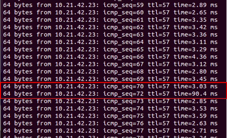
From the ping screen capture, the power off of the primary PGW vcg-40-sfpg01 cause 1 ping loss (between icmp sequence 70 and 72). The failover time is around 1-2 seconds. Since the failover time is a lot faster. The ping test is being performed again with the additional parameter “-i 0.1”, this means the ping will be send every 0.1s instead of the default which is sent every 1s. The following is the screen capture of the ping test result with 0.1s interval:
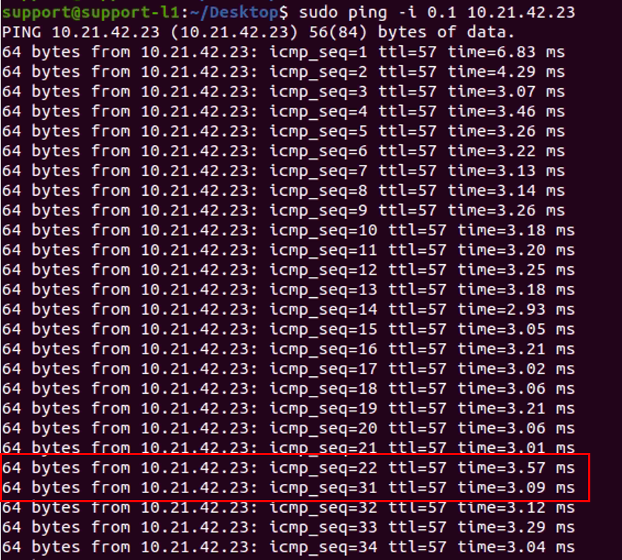
There are 8 ping loss (between sequence number 22 and 31), with each ping separate of 0.1s, this means 9 x 0.1s interval which result of 0.9s. As a result, it should be fine to conclude the failover time of the primary PGW failure is 1s with the BFD enabled BGP between PGW and PE router.
Maximum BFD session supported per PGW
As of version 4.0, the maximum number of BFD sessions supported on PGW is 250. Although this post is not talking about the BFD on SD-WAN Edge, for documentation purpose, the maximum number of BFD sessions supported in the SD-WAN Edge is 50.
This post “BGP with BFD enabled in SD-WAN Partner Gateway” ended here.